Digital Readout using Chinese digital Scale units (UPDATE 130922)
Some time back I decided that what my Perrin mill/drill needed was a DRO setup. I found the linear scales easily enough; every man and his granny seems to sell them these days, but Amadeal went one better and offered a display unit that allows up to three scales to be connected to give a relatively cheap DRO installation. There are a few limitations and provisos, of course: being battery-operated, the scales need to be mounted in such a way that the batteries can be accessed for replacement. The scales are not waterproof which precludes their use where flood coolant would be used; and the scales themselves are only capable of reading to .01 of a Millimetre or half a thousandth of an Inch. For me that's more than adequate, so I removed the table from the mill, worked out where and how best to mount the scales and tapped a few holes into the cast iron. Carefully running the table in both axes with a DTI touching the scales showed me where some shimming was needed to make sure the scales ran parallel to the ways and weren't distorted by the sliding head pulling or leaning on them.
I worked out a way to use a 1.5V regulator IC to give the scales a power feed from within the display head, but as the battery polarity is negative with respect to the display ground I had to use an old Nokia phone charger(!) to give an isolated supply. This worked, the scales were now powered from the display head, but the airborne interference generated by the 3-phase inverter made the displays read random gibberish.
Following advice on other websites I decided it was worth stripping the scale heads down and modifying them to be negative, rather than positive earth. This would allow the scales to be at ground potential with the mill chassis and inverter.
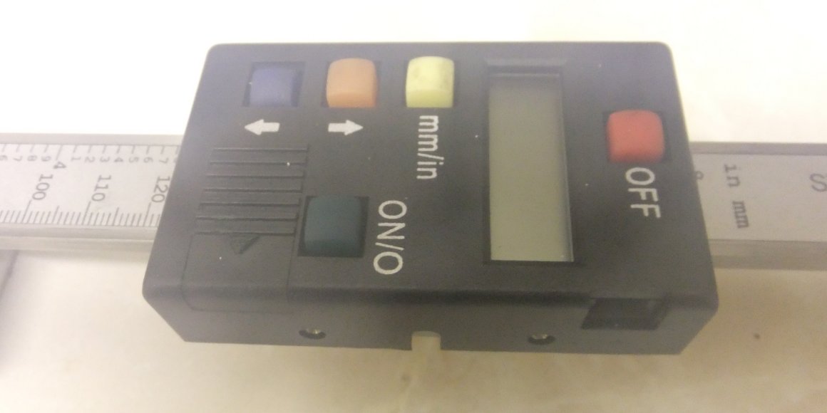
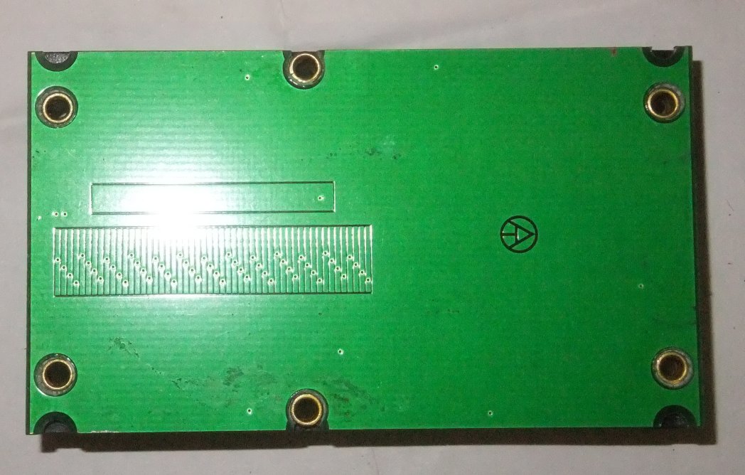
It's not a good picture (should have let the camera adapt to the change in temperature before I took the photo) but this is the design of scale I have:
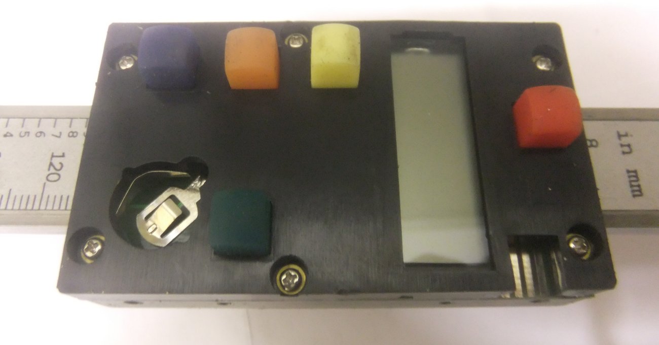
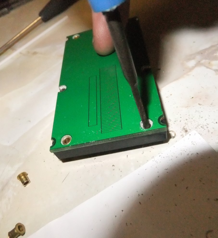
Removal of the three very small screws reveals this:
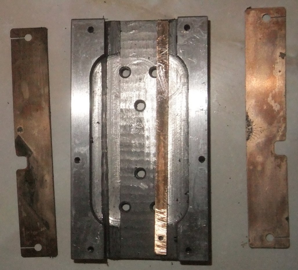
and removal of the six obvious screws allows the display module to be separated from the chassis:
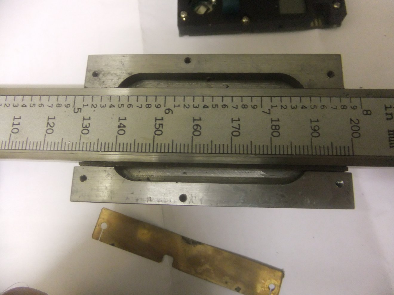
There's one thick brass bar acting as a gib strip (adjustable with two tiny grub screws) and two thin brass shims to set running clearance. If the whole thing falls apart in a pile it's not a huge problem to reassemble:
So, to business; to get the display module apart it's necessary to drill the heads off the brass rivets through which the mounting screws are installed. The 6 rivets clamp the PCB and its plastic housing together:
If you're a surgeon then you could probably drill the rivets out with a cordless drill; I'm too ham-fisted so I used a spot face cutter as used to cut the tracks on electronics Veroboard... it takes a bit of time and effort but is nicely controllable:
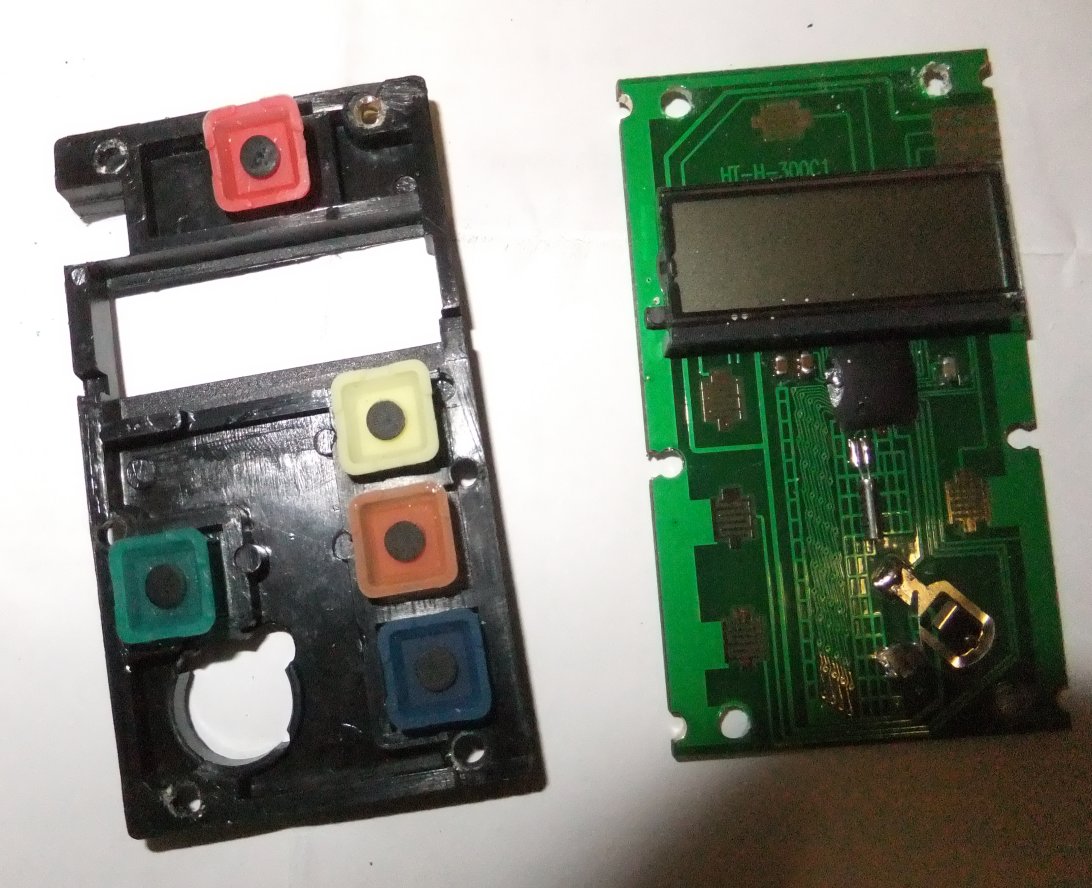
Once the rivets are out the board and housing will easily separate: you'll probably end up with the rubber buttons on the floor and the display detached from its conductive rubber... don't worry too much about this as it's easy enough to realign it, just try to make sure you know which way up the display should go as it lacks any obvious markings as to polarity:
In surgeon mode again, then, reach for the scalpel and cut the 'ground plane' areas from around the rivet holes. A quick glance would have you wondering how the thing will work afterwards as it appears that you isolate all of the switch contacts in the process. Trust me, you don't. There are 'through-hole' links at various points around the board so all will stay functional. Here I am making the first cut (didn't Rod Stewart say it was the deepest? 8^D ):
... and when finished you should have something like this:
You need to make sure that the copper is cleared far back enough from each hole that when you reinsert the rivets, they won't make contact anywhere... otherwise the ground plane, which is positive, will end up shorted to the chassis, which will be negative, with potentially catastrophic results for your power supply!
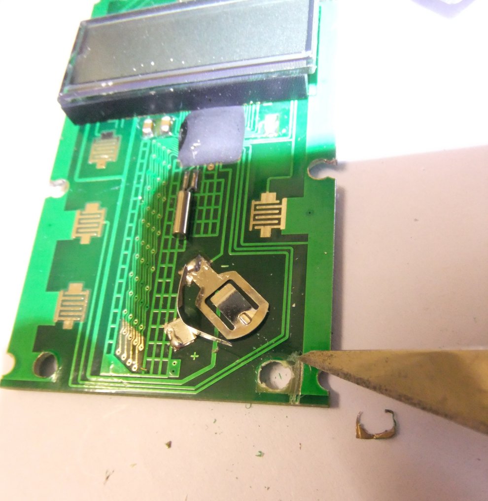
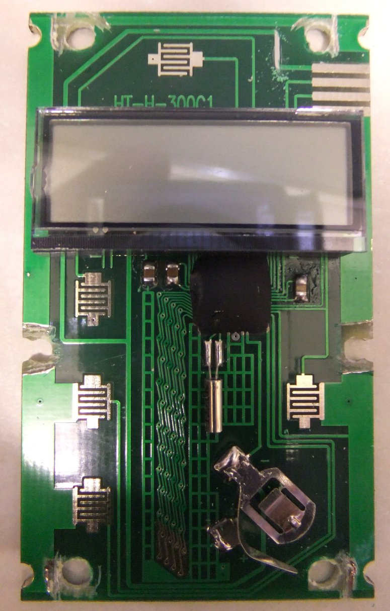
Next you need to add a couple of capacitors across the supply rails. The only place there's really room to do this is in the space normally occupied by the battery. I tried, I really did, to get the caps tucked away inside the housing but they were simply too bulky, so I gave up and soldered them across the battery terminals (polarity helpfully marked on the PCB, as you see).
If you look toward the top right corner of the board above you'll see an area of track that I've cleaned of green etch-resist with the scalpel. To this point solder a length of thin multi-strand wire, the sort of size you find in alarm system cable. Make it about three inches long, you can always trim it later. Have the wire leave the board directly in line with the track it's soldered to. You can then use the soldering iron to melt a small channel through the plastic cover edge to clear it. This wire will become the connecting link between PCB negative and the scale chassis.
Now, turn the board over and position two strips of thin adhesive tape (Sellotape or whatever) along the full length of the board for about a centimetre each side, leaving the centre of the board, with that cluster of tiny parallel tracks, clear. This will prevent the ground plane from contacting the scale chassis.
Then it's time to juggle the PCB, five buttons, display module, its contact strip and retaining bar, a piece of pink packing rubber, the plastic housing, six rivets, two brass strips and all the chassis metalwork, back into some semblance of order! Assuming you manage this, use a multimeter to check that there's no short between either battery terminal and the scale chassis. Now touch the bare end of the new wire to the chassis and you should be able to measure continuity from the battery negative terminal to the chassis, but not from the positive terminal to chassis. Phew. It may even work :O)
UPDATE 130922
The modified digital scales have been on the Perrin for some years now, and one thing that has become clear is that the connectors used on the DRO cables are pretty dire - not so much the 'RJ45'-style ones at the DRO end, but the ones used to connect to the scales themselves. On several occasions they've gone intermittent whilst in the middle of some milling task, with random zeroing and fluctuating readings causing no end of problems. Finally, I decided it was time to do something about it, but the only real solution was to cut the connectors off the cables and solder the wires directly to the PCB tracks at the edge connectors. I'll report back in another several years and let you know what happens :D